|
|
|
|
As pointed in About,
" urge the reader to use/trust the content only after verifying it against standards and/or consulting it with experts in the field".
|
»
|
5G (3GPP) standards are still being defined and written.
Due to an enormous success of LTE and vision of “connected world”, there is huge amount of interest in 5G.
On the other hand, due to shrinking profit margins, network operators are somewhat jittery about 5G
(do we at all need it and is the cost justified ?).
All in all, there seems to be confusion and lack of clarity in 5G !
Below article takes a step back and check reasons behind 5G requirements.
This shall help in providing clarity of where 5G is heading to.
|
5G Intent
|
|
Also, have a look at,
|
5G Intent for Modem developer (a presentation)
|
|
|
»
|
|
Few 3GPP 5G terms
|
|
5G Air interface
|
New Radio (NR)
|
|
5G Node B
|
gNB
|
|
eNBs enhanced for 5G
|
eLTE eNB
|
|
5G Radio Network
|
Next Generation RAN (NG-RAN)
|
|
5G Core Network
|
Next Generation Core (NGC)
|
|
|
|
»
|
|
5G architecture options
|
|
Refer below 3GPP document for exhaustive list of considered options.
|
RP-161266
|
Below diagram shows these options in certain logical manner (38.801:7.2):

Option 1
|

|

|
Option 3/3A
|

Option 3x (EN-DC)
|

|

|
Option 7/7A
|

|

|
Option 4/4A
|

Option 5
|

Option 2
|
Further, 3GPP TR 38.801 section 14
shows possible migration paths towards NR using these architecture options.
Do not confuse these with RAN (CU-DU) split options (38.801:11).
|
|
|
»
|
|
CDF
|
|
CDF stands for Cumulative Distribution Function.
This has been extensively used in 3GPP technical reports to compare design/deployment options,
e.g. Rel 10 Carrier aggregation Vs Dual Connectivity during Rel 12 design.
It is worth while to take a look at CDF and what it represents.
Refer below article.
|
CDF explained
|
|
|
»
|
|
Small cells enhancements in LTE
|
|
Number of 5G design points were result of observations made and learnings learned in LTE and LTE-Advanced.
Below article looks at LTE enhancements that were made for (or helped) Small cells.
|
Heterogenous Networks and Small cells in 3GPP
|
|
|
»
|
|
Definition of NR frequency ranges (FR)
|
3GPP TS 38.101-1 defines below frequency ranges:
|
FR1
|
410 MHz – 7.125 GHz (aka Sub-6 GHz)
|
|
FR2
|
24.25 GHz – 52.6 GHz (aka mmWave)
|
|
|
|
»
|
|
5G NR Numerologies
|
5G NR specify configurations with different carrier spacings, aka numerologies !
|
μ
|
Δf kHz
|
Slots per subframe
|
Symbols per subframe
|
FR
|
|
0
|
15
|
1
|
14
|
FR1
|
|
1
|
30
|
2
|
28
|
FR1
|
|
2
|
60
|
4
|
56
|
FR2
|
|
3
|
120
|
8
|
112
|
FR2
|
|
4
|
240
|
16
|
224
|
-
|
Subcarriers per RB = 12 (constant)
Symbols per slot = 14 (constant)
Subframes per frame = 10 (constant)
One frame = 10ms (constant)
One subframe = 1ms (constant)
Symbol timings:
|
μ
|
Δf kHz
|
Microseconds
|
Nanoseconds
|
|
0
|
15
|
71.429
|
71428.571
|
|
1
|
30
|
35.714
|
35714.286
|
|
2
|
60
|
17.857
|
17857.143
|
|
3
|
120
|
8.929
|
8928.571
|
|
4
|
240
|
4.464
|
4464.289
|
Slot timings:
|
μ
|
Δf kHz
|
Microseconds
|
|
0
|
15
|
1000.006
|
|
1
|
30
|
499.996
|
|
2
|
60
|
249.998
|
|
3
|
120
|
125.006
|
|
4
|
240
|
62.496
|
μ=0 configuration is almost same as LTE configuration (except no support for extended cylic prefix in NR).
|
|
|
»
|
|
Point A in 5G NR
|
LTE (PHY) resource grid is based on constant carrier spacing of 15 kHz.
5G NR specify multiple carrier spacings (15,30,60,120,240 kHz).
Multiple resource grids with different carrier spacings may exist within the same bandwidth (carrier).
A reference point is needed from which various resource grids can be located or mapped.
This reference point is Point A.
SSB (Synchronisatioon Signal Block or PSS/SSS/PBCH block) is the first clue to get to Point A.
To understand better, let us take an example of LTE.
Let us say subcarrier 0 of RB (physical resource block) 0 is our LTE reference point or LTE Point A.
As SSB is located at the center of bandwidth in LTE, based on bandwidth information decoded from PBCH/MIB, LTE Point A can be located.
LTE Point A would at half of bandwidth away from center of SSB.
Refer LTE DL PHY Structure Example (15 RB, 3 MHz) for visualisation.
Let us check for 5G NR now.
5G NR has concept of "common resource blocks (CRB)" - which may not have same subcarrier spacing as SSB.
Let us make subcarrier 0 of CRB 0 as our Point A.
Due to differences in subcarrier spacing between common resource blocks and SSB,
center subcarrier of SSB may not match to any subcarrier of overlapping common resource block !
So to get to Point A (from SSB), we need two parameters - first to get to nearest subcarrier (kSSB) of overlapping CRB
and then number of this overlapping CRB (basically location of this CRB from Point A) - NCRBSSB.
|

|
kSSB information come from MIB and NCRBSSB from SIB1.
Refer 3GPP TS 38.211:4.4.4.2/4.4.4.3/7.4.3 for more details.
Above discussion also imply that unlike LTE, SSB may not be located at the center of bandwidth (carrier).
|
|
|
»
|
|
5G NR Resource grid
|
|
Below page illustrate two resource grids within two numerologies (15 kHz and 30 kHz).
Point A is subcarrier 0 of CRB 0 - common for all numerologies.
Resource grid would be away from Point A by offsetToCarrier.
This suggest that Point A could even lie outside reserved (usable) bandwith.
|
5G NR Resource grid illustration
|
|
References: 3GPP TS 38.211:4.4.2.
|
|
|
»
|
|
5G NR Bandwidth part
|
BWP is described with locationAndBandwidth (in RIV format) and subcarrier spacing.
RIV indicate Start CRB and Size of BWP in terms of RBs.
To know more about RIV format, refer this LTE article,
replace NRBDL with NBWPsize = 275.
Below page illustrate two resource grids and one bandwidth part in each.
From specification,
"A UE can be configured with up to four bandwidth parts in the downlink with a single downlink bandwidth part being active at a given time."
Same is true for Uplink.
|
5G NR Bandwidth part illustration
|
|
References: 3GPP TS 38.211:4.4.5,
3GPP TS 38.331 BWP
|
|
|
»
|
|
5G NR SSB candidate locations in half frame
|
3GPP TS 38.213:4.1 "Cell search" specify procedure to determine SSB candidate locations.
As the word "candidate" suggest, these are possible locations - SSB may not be sent in all locations.
Each candidate location has SSB index; index start with 0 and goes till 4,8,or 16.
Both location and index depend on the selected numerology for SSB reception and frequency range (FR1/FR2).
SSB index is embedded in DMRS and few of PBCH bits.
Below is an illustration for FR1.
|
5G NR SSB candidate locations in half frame (illustration)
|
|
|
»
|
|
5G NR CORESET PDCCH versus LTE PDCCH
|
If we compare NR CORESET# 0 illustration with
LTE one (LTE DL PHY example for 1.4MHz),
LTE PDCCH seem like a special case of NR CORESET PDCCH !
Another interesting comparision is between LTE Cat M1 MPDCCH and NR one.
Requirement being low complexity, LTE eMTC devices operate on 6 RB bandwith
and makes use of (EPDCCH based) MPDCCH rather than PDCCH
(refer Cat M1 article).
NR, by its design, allow smaller (to larger) bandwidth PDCCH search spaces.
Each bit of frequencyDomainResources of ControlResourceSet IE correspond to 6 RBs !
References: 3GPP TS 38.213:10.1,
3GPP TS 38.331:6.3.2 ControlResourceSet.
|
|
|
»
|
|
5G NR REG, REG Bundle, and CCE
|
LTE REG and 5G NR REG differ.
LTE REG is four resource elements (refer article here).
5G NR define REG (Resource Element Group) as tweleve consecutive resource elements (of 1 RB).
In a way, one REG is one RB over one symbol.
REG bundle is a group of REGs.
A CCE (Common Control Element) consists of one of more REG bundles.
The bundles of a CCE may be consecutive (non-interleaved) or not (interleaved).
Below is an example of CORESET# 0:
first map shows complete CORESET# 0,
second one shows REGs of the CORESET,
third one shows REG bundles, and
fourth shows CCEs (CCE contain one bundle).
Refer 3GPP TS 38.211:7.3.2.2 for more details.
|
CCE-to-REG mapping for CORESET# 0 illustration
|
|
|
»
|
|
Initial flow at 5G UE
|
Keeping LTE in mind, if we look at 5G, it is parameters like
SCS, Point A, Resource grid, CORESET, BWP, REG bundles so on - different from LTE - that play roles in determination of RF resources.
Band and SSB SCS determination
(38.101-1:Table 5.4.3.3-1)
|
|
|
SSB detection
kSSB
SIB1 SCS
CORESET# 0
Type-0 CSS
|
(38.211:7.4.3)
|
|
|
SIB1 acquisition
offsetToPointA
Resource grids:
SCS,
carrierBandwidth,
offsetToCarrier
initialDownlinkBWP
|
(38.211:4.4.2/4.4.4.2/4.4.4.3/7.4.3)
|
|
|
Further SIB acquisitions
|
|
|
|
»
|
|
5G NR FAPI specification
|
SCF222
|
|
LTE FAPI/nFAPI (SCF082) specification is here.
|
|
|
»
|
|
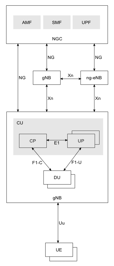
5G network architecture (simplified)
|
|
|
AMF
|
Access and Mobility Management Function
|
|
CU
|
Central Unit
|
|
CP
|
Control Plane
|
|
DU
|
Distributed Unit
|
|
SMF
|
Session Management Function
|
|
UP
|
User Plane
|
|
UPF
|
User Plane Function
|
References: 3GPP TR 38.801:7.1,
3GPP TS 38.401:5.1/6.1, and
3GPP TS 38.300:4.
|
|
|
»
|
|
CU-DU split
|
gNB functionality is (logically) split in CU and DU.
Options 1 to 8 are explored in 3GPP TR 38.801:11.
Based on the split option, there would be bandwidth and latency requirements on the interfaces between CU, DU, and RU.
For example, at Option-6 interface (MAC-PHY), major information flow is transport block flow,
at Option-8 (RF separated from rest of PHY) interface, it would be flow of DSP IQ samples,
which may require 40 times more bandwidth than TB flow.
Refer 38.801:Annex A.
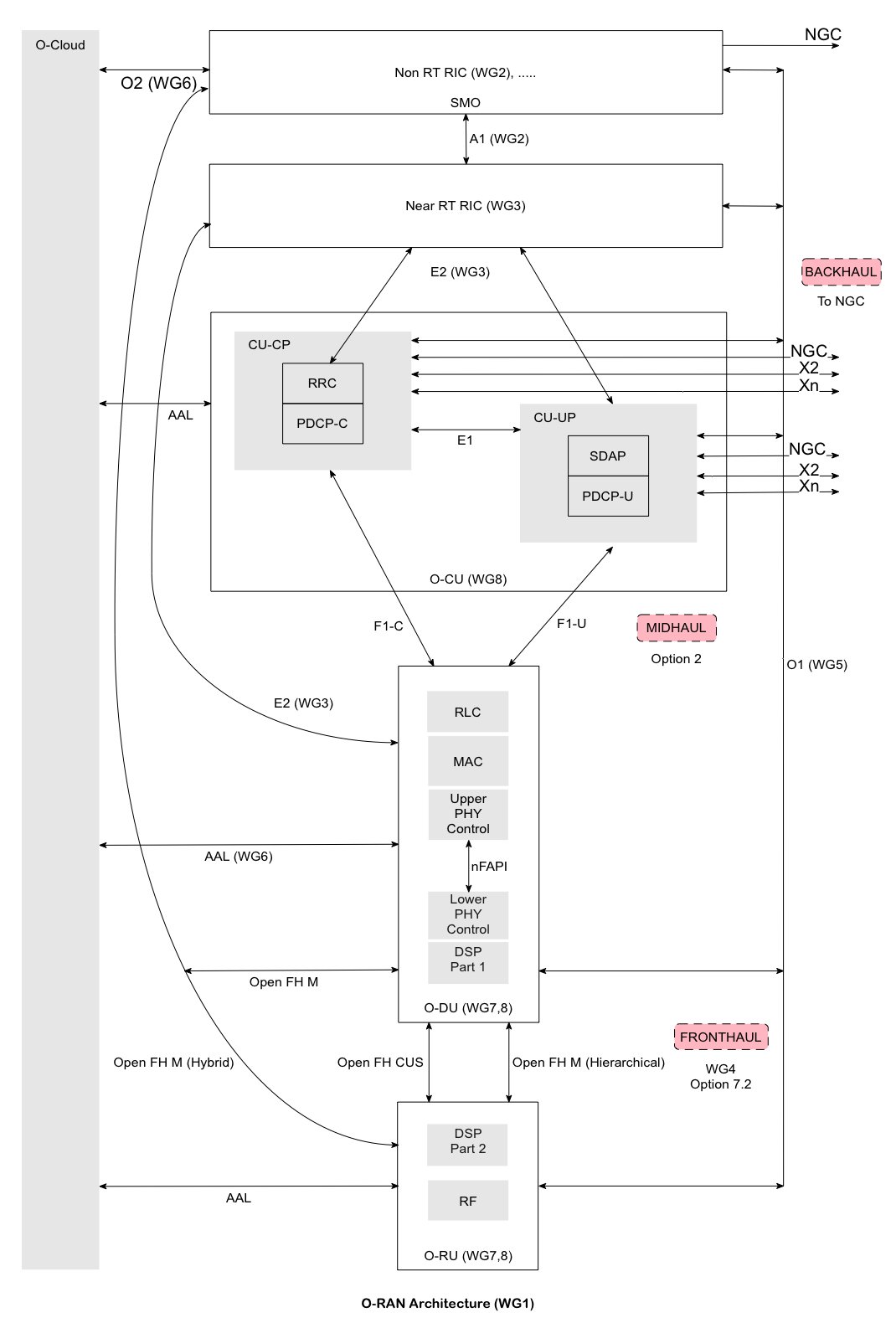
O-RAN use options 2 and 7 to split gNB in CU, DU, and RU (Radio Unit).
Refer ORAN architecture document is "O-RAN.WG1.O-RAN-Architecture-Description" at ORAN Specification page.
|

|
References: 3GPP TR 38.801:11, Annex A.
|
|
|
»
|
|
5G NR illustrations
|
Below is list of all above illustrations:
|
|
|
»
|
|
Generic PHY architecture
|
Whether it is RAN (eNB/gNB) or UE (Modem), PHY architecture is similar in certain aspects.
RAN/UE platform documents will usually depict their design in terms of hardware and software architecture diagrams.
Below are generic hardware and software architectures.
Software architecture view is more of logical/functional view.
|

|
|
Software architecture
Hardware architecture view separate out software/logical components as per physical separation of their processors/hardwares.
|

|
|
Hardware architecture
|
DSP
|
Digital Signal Processor
|
|
OS
|
Operating System (usually real time like ARM)
|
|
OSC
|
Oscillator (a.k.a. Crystal)
|
|
RAT
|
Radio Access Technology like GSM, UMTS, LTE, or 5G.
|
|
RF
|
Radio (frequency) unit
|
In case of multi-mode (GSM/UMTS/LTE/5G) design, each RAT may have their separate hardware and software architectures
with a method of exchange/synchronisation between RATs at both software and hardware levels. Needless to say, complexity only
increase with each inclusion of RATs and inter-RAT features.
|
|
|
»
|
|
O-RAN Architecture, Interfaces
|
|
Below is O-RAN architecture, interfaces, and working group pointers.
|
|
References: ORAN Specifications.
|
|
|
»
|
|
PRACH occasions
|
|
Below is top level view of PRACH occasions in time and frequecy domains.
|

|
Format
Sequence length
|
SCS (kHz)
|
Number of RBs
|
Duration
|
Long
839
|
1.25 or 5
|
~6 or ~24 RBs
(15 kHz SCS)
|
A slot or more
|
Short
139
|
NR SCS
|
12 RBs
|
Multiple in a slot
|
References: 3GPP TS 38.213:8,
3GPP TS 38.211:6.3.3
|
|
|
»
|
|
Converting 5G NR Timing advance to Distance
|
We could use timing advance to find out the distance between UE and base station.
As timing advance is timing separation between DL and UL as seen at UE, it would
account for propagation delay for DL plus propagation delay for UL.
If we divide speed of light by timing advance and halve it, we would
get the distance between UE and base station.
Below is formula for finding timing advance.
TTA = (NTA + NTA,offset) * Tc [38.211:4.3.1]
NTA,offset is a cell level parameter, configured via SIB1/n-TimingAdvanceOffset.
If not set, it is 25600 (FR1), 0 (FR1/LTE coexistence/FDD), 39936 (FR1/LTE coexistence/TDD).
For FR2, it is always 13792 [38.213:4.2, 38.331:n-TimingAdvanceOffset].
NTA,offset being cell level parameter, this map to timing separation between
DL and UL at base station ! Thus to find the distance
between UE and base station, we take only NTA.
Tc is time unit, mapping to maximum sampling frequency (SCSmax * FFT sizemax) [38.211:4.1].
Tc = 1 / (480 kHz * 4096 ) = (1/1966080) ms
NTA = TA * 16 * 64 / 2μ [38.213:4.2]
TA (timing advance) range from 0 to 3846. Taking TA=1 and μ=0 (SCS=15 kHz),
NTA = 1 * 16 * 24 / 20 = 1024
TTA = (1024 + 0) * (1/1966080) ms = (1/1920) ms = (1/1920000) sec = 0.520833 us = 520.833 ns
Distance between UE and base station for TA=1 is (299792458/1920000)/2 = 78.071 meters !
Maximum distance i.e maximum cell radius would be 78.071 * (TA=3846) = 300.261 km.
Above calculation was done for SCS=15 kHz. As NTA is inversely proportional to 2μ,
above values can be halved for each further numerologies.
Note about LTE: LTE too had NTA,offset.
It was 0 for FDD and
for TDD, it was 624 * Ts = 624 * (1/30.720000) μs = ~20 μs.
As 624 * Ts = 39936 * Tc, NTA,offset is 39936 for FR1/LTE coexistence/TDD !
|
|
|
»
|
|
Maximum number of RBs per bandwidth (FR1) as per numerology
|
Channel bandwith minus guard periods (at egdes) gives us transmission bandwidth.
Below table for is quick reference for transmission bandwidth converted into RBs.
| BW |
15kHz |
30kHz |
| 5 |
25 |
11 |
| 10 |
52 |
24 |
| 15 |
79 |
38 |
| 20 |
106 |
51 |
| 25 |
133 |
65 |
| 30 |
160 |
78 |
| 40 |
216 |
106 |
| 50 |
270 |
133 |
| 60 |
- |
162 |
| 70 |
- |
189 |
| 80 |
- |
217 |
| 90 |
- |
245 |
| 100 |
- |
273 |
Ref: 3GPP TS 38.101-1:5.3.1
|
|
|
»
|
|
Finding FFT size for a bandwidth and SCS configuration
|
As per OFDM theory, FFT size (samples per OFDM symbol) is to be at least the number of subcarriers.
| BW |
15kHz |
30kHz |
| 5 |
512 |
256 |
| 10 |
1024 |
512 |
| 15 |
1536 |
768 |
| 20 |
2048 |
1024 |
| 25 |
2048 |
1024 |
| 30 |
3072 |
1536 |
| 40 |
4096 |
2048 |
| 50 |
4096 |
2048 |
| 60 |
- |
3072 |
| 70 |
- |
3072 |
| 80 |
- |
4096 |
| 90 |
- |
4096 |
| 100 |
- |
4096 |
Ref: 3GPP TS 38.101-1:Annex F.5
|
|
|
»
|
|
Modulation scheme and order
|
Modulation scheme and corresponding order value for DL(PDSCH) and UL (PUSCH) are as below:
| Scheme |
Order |
| π/2-BPSK* |
1 |
| QPSK |
2 |
| 16QAM |
4 |
| 64QAM |
6 |
| 256QAM |
8 |
*: UL transform precoding enabled.
Modulation order indicate number of bits in an OFDM symbol.
Ref: 3GPP TS 38.211
|
|
|
»
|
|
About RAN timing control
|
For air interface to succeed, UE need to be synchronised to the base station, both in frequency and time domain.
Though not apparent, it also means that the base station need to maintain its transmission time interval (TTI) with the accuracy of nanoseconds.
Within ORAN based gNB, Scheduling, Phy procedures, DSP, and RF processing must work in tandem to ensure the timing over the air.
As RU and DU are physically separate, a common timing reference is needed.
This is provided by PTP Grandmaster (Fronthaul S plane).
Within DU, synchronisation between above mentioned processes is achieved by setting certain time limit on each.
This time limit could be in the units of TTI (slot time) or Symbol timing.
|

|
On UE side, an internal clock is kept in sync with the base station with the receptions of SSB, CSI-RS, and PDCCH/PDSCH.
|

|
Clocks shown above are not necessarily hardware (programmable) clocks, it could be virtual/software clocks or combinations of both.
|
|
|
»
|
|
About NSA Options 3/3a/3x (EN-DC)
|
Options 3/3a/3x are essentially extensions of one of LTE Release 12 features, called "Dual Connectivity".
In all the options, eNB acts as a Master node and gNB acts as a Secondary node.
In Option 3, with eNB configuration changes, 5G NR cell can become part of LTE RAN.
However, eNB (and X2 interface) will have to support 5G NR throughput.
|

|
In Option 3a, with RAN/CN configuration changes, 5G NR cell can be introduced, connected directly to EPC.
Disadvantage is: if there are not enough 5G NR cells, UEs will have to be handed over to LTE cells via slower procedure at EPC.
In Option 3, this is not the case as bearers are split at eNB.
|

|
In Option 3x, bearer is split at gNB (eNB remain a Master node).
In a way, this option seems better than above two options.
Yes, it requires software enhancement at eNB.
|

|
Ref: 3GPP TR 38.801,
3GPP TS 36.300
|
|
|
»
|
|
Terminology: Paired/Unpaired
|
3GPP TS 38.211 refers terms Paired and Unpaired specturms to indicate FDD and TDD arrangements respectively.
|
|
© Copyright Samir Amberkar 2018-24
| |
| |
|
|